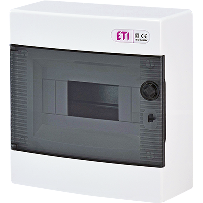
Selected Requirements for the Design and Development of Enclosures for Low-Voltage Switchgear by ETI
When designing low-voltage switchgear, many manufacturers follow guidelines from standards to create and market a product that meets all necessary requirements and ensures safety.
The main standards and regulations used by manufacturers in their projects are:
– LVD 2014/35 EU Low Voltage Directive,
– SIST EN 62208 standard,
– SIST EN 61439 series of standards (SIST EN 61439-1, SIST EN 61439-2, SIST EN 61439-3, SIST EN 61439-4, SIST EN 61439-5, SIST EN 61439-6).
In the European Union, the legal basis for all electrical equipment with voltages ranging from 50 V to 1,000 V AC and from 75 V to 1,500 V DC is the EU Low Voltage Directive LVD 2014/35. Its purpose is to ensure protection, ensuring that electrical equipment in use does not endanger the safety of people, animals, or property.
Manufacturers of switchgear confirm compliance with the provisions of the EU LVD 2014/35 directive with a declaration of conformity or certification. If the legal requirements are not met, the user of the switchgear may be exposed to danger.
Another normative provision that specifies requirements for empty enclosures for low-voltage switchgear and control gear is the SIST EN 62208 standard. It applies to empty enclosures supplied by the manufacturer before the user installs switchgear and control devices [2].
This standard includes all definitions, classifications, characteristics, and testing requirements for enclosures used as parts of switchgear and control gear, even when complying with the SIST EN 61439 standard, with a rated voltage not exceeding 1,000 V AC at a frequency not exceeding 1,000 Hz, or 1,500 V DC. It is designed for general use both outdoors and indoors. Compliance with the safety requirements of the applicable product standards is the responsibility of the original manufacturer (manufacturer of the enclosure or switchgear enclosure system) and the set manufacturer (manufacturer assembling the devices, equipment, and connecting circuits).
The original manufacturer is responsible for producing the enclosure so that the set manufacturer, who is responsible for assembling the apparatus, equipment, and wiring of the switchgear, can meet the requirements of the SIST EN 61439 standard.
The set manufacturer (of the completed switchgear) must follow the recommendations of the original manufacturer. In some cases, the original manufacturer may also be the set manufacturer.
For low-voltage switchgear and control gear that are already available, the SIST EN 61439 standard contains key information. It defines the division of responsibilities and requirements for the preparation and construction of low-voltage switchgear.
One of the main objectives of introducing this standard is to improve the safety level during the operation and maintenance of switchgear, considering where the switchgear is installed and operates. The proper selection of internal equipment is critical for the actual functioning of the switchgear. In addition to standard operating parameters of the switchgear, such as humidity, ambient temperature, and pollution levels, specific operating conditions are also defined. These could be special conditions present at a specific usage location. The standard emphasizes the role of the user, who must inform the switchgear manufacturer (set manufacturer) about such conditions, and they, in turn, must inform the enclosure manufacturer (primary manufacturer) about any potential issues. Examples of special conditions include: critical temperature values, aggressive acidic environments, the presence of dust or other corrosive particles, electromagnetic radiation, UV radiation, etc. [2,3].
This standard specifies numerous parameters that the switchgear must meet. For example, the indicated diversity factor (RDF) is the rated current value in relative units (assigned by the manufacturer to the "set") up to which certain consumer circuits of the set can be continuously and simultaneously loaded, considering mutual heat exchange. Calculating this factor is not straightforward. Data is required on the amount of heat generated by all installed electrical devices, busbars, conductors, or at least the heat energy exchange with the environment (which depends on the design of the switchgear, enclosure surface, and ambient temperature) [2].
Declarations of conformity are issued by manufacturers after assembling the final switchgear. This confirms that the switchgear has been manufactured in compliance with the SIST EN 61439 standard.
To verify the design of the switchgear, the standard recommends using three available methods of verification. The first method is testing the completed set under real conditions, which is not easy since not every production facility has a laboratory capable of performing such tests. The next method is comparing the switchgear to an identical already-tested switchgear. The most common method is product verification, which includes verifying parameters, the original manufacturer's declarations (e.g., enclosure), conducting tests, and calculations if all necessary data for calculations is available.
An empty enclosure for low-voltage switchgear, as defined in the SIST EN 62208 standard, is an enclosure designed to house and support installed switchgear and control devices. It provides adequate protection against external influences with a specific degree of sealing and a certain level of protection against proximity or contact with live parts or moving parts [2,3,4,5].
Each manufactured enclosure must have appropriate identification labels. These details must be legible and permanent, preferably located on the interior of the enclosure in the form of a nameplate or engraving, e.g., on the enclosure doors.
An important element is also the manufacturer's documentation for the manufactured enclosure. This documentation must include information such as:
– design characteristics,
– mechanical characteristics,
– classification of the enclosure,
– instructions for proper use,
– installation and operating conditions.
If necessary, reference can also be made to a standard that precisely describes additional required parameters, such as:
– dimensions and installation method,
– allowable load,
– measures for protection against electric shock,
– equipment required for handling and transport of enclosures,
– operating conditions,
– heat dissipation capacity,
– location and size of the protected space,
– rated insulation voltage for enclosures made of insulating materials,
– IP and IK protection levels.
All data on external dimensions are usually specified in [mm] in the manufacturer's catalog. These dimensions must not include projections of cable entries or sides of the enclosure and brackets that cannot be screwed in. Generally, this must be stated in the documentation prepared by the manufacturer [2].
The heat dissipation capacity of the enclosure depends on the permissible temperature within the enclosure, considered for different enclosure installation methods (flush-mounted, surface-mounted, freestanding), for enclosures with ventilation openings, or enclosures with different numbers of horizontal partitions. This information must include at least the temperature increase within the enclosure at the top and the possible temperature increase on external surfaces under given energy losses within the enclosure. This allows the user to select an enclosure tailored to their equipment and intended installation location [2,3].
An extremely important element in any enclosure is ensuring the continuity of electrical connections through a separate protective conductor or conductive components. Circuit continuity must be maintained even if a removable part of the enclosure, such as a side or internal mounting bracket, is removed. For doors, fronts, and other metal components, it is assumed that metal connections, e.g., hinges, screw connections, ensure circuit continuity if no electrical equipment is attached to them. Otherwise, a separate PE conductor must be screwed in.
Normal and Special Operating Conditions for Empty Switchgear Enclosures
Enclosures from manufacturers meeting the SIST EN 62208 standard requirements are designed for indoor and outdoor use. Each manufacturer must specify exactly where the enclosure can be installed.
An important parameter describing operating conditions is ambient temperature. For indoor and outdoor use, the temperature is the same and must not exceed +40 °C, with a 24-hour average not exceeding +35 °C. The only difference is the lower ambient temperature limit, which is -5 °C for indoor use and -25 °C for outdoor use.
Another parameter defining operating conditions is the humidity level at the location. These values differ for indoor and outdoor use. Relative humidity for indoor use must not exceed 50% at the highest temperature of +40 °C. At lower temperatures, higher humidity levels are allowed, e.g., 90% at +20 °C. Temperature differences and high humidity can lead to occasional condensation, which is an undesirable phenomenon [2].
Figure 1. Condensation of water vapor inside a switchgear due to rapid temperature changes outside the switchgear in high humidity conditions if proper internal ventilation is not ensured – foreign design and solution
Relative humidity in outdoor use can occasionally reach 100% at a maximum temperature of +25°C.
Enclosures are sometimes installed in locations with specific climatic and environmental conditions, which are defined by the particular operating conditions of the enclosures. The user and manufacturer must agree on the requirements for the operating conditions of the enclosure. The most common specific operating conditions encountered are:
– unusual ambient humidity and temperature,
– the potential presence of corrosive substances,
– the presence of dust (cement, coal, etc.),
– local presence of mold, animal, or plant species (e.g., rodents or ants),
– electrostatic and ionizing interactions,
– electromagnetic interference,
– vibrations and oscillations,
– ultraviolet radiation not caused by sunlight,
– mechanical stress caused, for instance, by seismic shocks.
Construction Guidelines for Empty Switch Enclosures
During construction, it is assumed that the enclosure must be made of materials resistant to various exposures, such as mechanical, thermal, or electrical stress caused by short circuits or other external factors. To protect against corrosion, enclosures are made from special materials (e.g., INOX versions) or are coated with special protective layers on surfaces exposed to corrosion, depending on the prevailing conditions at the installation site.
Each enclosure must be designed to allow access to its interior, particularly to the protected area. This access must only be possible with a key or tool, by removing the frame or a removable cover (e.g., unscrewing the rear cover of the enclosure).
Figure 3. Polyurethane gasket cast on the doors and rear side of switchgear enclosures manufactured by ETI
To achieve a higher IP protection rating, special polyurethane gaskets are used, cast directly onto the component. These gaskets ensure a very high level of sealing as there are no unnecessary sealing joints.
When designing a switchgear enclosure, special attention must be paid to maintaining appropriate clearance and creepage distances. These requirements are detailed in standard PN-EN 60664-1 [10]. The distances must be preserved to ensure that installed electrical devices and other equipment within the switchgear do not alter the specified insulation distances.
If separate circuits are intended within the switchgear, overvoltage levels must be considered to ensure that clearance and creepage distances between these circuits are maintained. For busbars, equipment terminals, and cable connections (all uninsulated components), at least the insulation distances specified for the connected equipment must be ensured. It is understood that a short circuit between the busbars or their terminals must not permanently reduce the provided insulation distances.
To increase insulation distances, special protruding grooves are used in insulating elements, significantly increasing the creepage and clearance distances [2,3]. With concave grooves, only the creepage distance is increased.
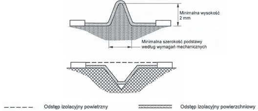
Figure 4. Example of clearance and creepage distance [10].
Type Testing of Low-Voltage Empty Switchgear Enclosures
During type testing of low-voltage enclosures, it is essential to test the installed and assembled enclosures as they would be used under normal conditions. These tests are typically conducted at ambient temperatures between +10°C and +40°C, unless otherwise specified in the testing requirements. The procedure for type testing enclosures is detailed in standard SIST EN 62208, which precisely defines what must be tested and how the testing procedure should be carried out.
These tests are performed on complete enclosures; however, in some cases, this may not be feasible, so, for example, a sample cut from the enclosure may be tested instead. All these tests are summarized in the table below, which provides a detailed overview of the types of tests conducted on low-voltage enclosures [2]
Table 1. Type tests performed with the number of samples and sequence of tests on the samples in accordance with [1]
| Test | Sample 1 | Sample 2 | Sample 3 | Representative Sample |
|---|---|---|---|---|
| Marking | 8 | |||
| Static loads | 1 | |||
| Lifting | 2 | |||
| Axial load on metal mortar | 3 | |||
| Protection level against external mechanical impacts (IK rating) | 4 | |||
| Protection level against access to hazardous parts and penetration of solid objects and/or water (IP rating) | 5 | |||
| Thermal stability | 1 | |||
| Resistance to normal temperature | 2 | |||
| Resistance to heat and fire | 3 | |||
| Dielectric strength | 6 | |||
| Continuity of the protective circuit | 7 | a | ||
| Resistance to ultraviolet (UV) radiation | ||||
| Resistance to corrosion | 2 | |||
| Heat dissipation performance | 1 (b) |
- a – Tests are performed only on the representative sample.
- b – Applies only if the test has been conducted.
All these tests are carried out by accredited laboratories, which issue a test report and certificate upon completion. Testing can also be conducted in other laboratories equipped to perform the specific type of test, such as corrosion resistance testing in salt chambers or dielectric strength testing in laboratories, for instance, at technical faculties.
These tests allow us to confirm the design assumptions and determine whether additional work is needed to improve the design of the created structure.
Every enclosure manufactured by the producer must be labeled with a laminated plastic tag, embossing, or engraving. The label must include information such as [2]:
– the manufacturer's catalog number,
– the type of the enclosure,
– a description, preferably in multiple languages,
– the overall dimensions of the enclosure,
– symbols of obtained certifications.
Testing a specific label is performed by rubbing it manually for approximately 15 seconds with a cloth slightly moistened with water, followed by another 15 seconds with a different cloth moistened with white spirit. After this procedure, all information on the test label must remain clearly readable without difficulty.
Enclosures are designed during construction to withstand specific static loads. Static load tests verify these assumptions after the production of the respective enclosure. To perform these tests, the enclosure must be equipped with all necessary components to withstand the maximum permissible load. During the test, a load of 1.25 times the maximum specified by the manufacturer is applied. The load is evenly distributed across the mounting supports, mounting plate (intended for switchgear and control devices), and doors, applying stress to these components for one hour. If the enclosures are made of plastic or if metal enclosures feature plastic hinges or locks, this test is conducted at 70°C, during which the doors are opened to a 90° angle five times and remain open for at least one minute [2]. After the test, the enclosure must retain all its original properties without any damage, visible cracks, or deformations.
To facilitate the lifting and transportation of enclosures for the customer, enclosures are tested under load during type testing. The manufacturer determines the methods and means of moving the enclosure. During the first phase of the test, the enclosure is moved vertically three times from the starting point to the designated endpoint. In the next phase, the enclosure is lifted to a height > 1 meter and held stationary for 30 minutes. The final procedure involves lifting the loaded enclosure to a height of more than 1 meter, transporting it horizontally for approximately 10 meters, and then lowering it. This process is repeated three times at a constant speed as recommended by the standard. After the test, the enclosure must retain all its original properties and remain undeformed.
Enclosures often contain metallic clamping elements that enable proper attachment of mounting plates or supports within the enclosure. These elements have their own rated load capacity, which is verified through axial load testing. This test is conducted for all types of enclosures with threaded pressed components. During the test, the enclosure must be adequately protected to allow the application of the load.
The test is performed on representative samples exposed to axial forces for 10 seconds. The forces applied vary depending on the metric thread size, as shown in the table below.
Table 2. Values of applicable forces based on metric thread size in accordance with [2]
| Thread Size (Mⁿ) | Axial Load (N) |
|---|---|
| 4 | 350 |
| 5 | 350 |
| 6 | 500 |
| 8 | 500 |
| 10 | 800 |
| 12 | 800 |
Mⁿ – Metric thread size
After testing, the test is considered successful if the pressed components remain in their original position without distortion or looseness. Cracks or fractures in the material of the pressed components are also unacceptable. Only minor cracks and bubbles observed before the test and unrelated to the load are disregarded.
An important parameter for any enclosure is the IK protection rating, which indicates the level of protection against external mechanical impacts provided by the enclosure. For this purpose, testing is performed using a test hammer, selected based on the size of the enclosure, in accordance with the SIST EN 62208 standard.
During the test, the enclosure is mounted on a rigid base to simulate its typical use [2,3,9]. Impact testing is then carried out on the enclosure, with the number of impacts determined by the size of the surface. For surfaces where the largest dimension does not exceed 1 meter, three impacts are applied. For surfaces exceeding 1 meter, five impacts are applied. The impact force varies according to the IK protection level.
Table 3. Impact energy values for individual IK levels
| IK Level | Impact Energy |
|---|---|
| IK01 | 0.14 J |
| IK02 | 0.2 J |
| IK03 | 0.35 J |
| IK04 | 0.5 J |
| IK05 | 0.7 J |
| IK06 | 1 J |
| IK07 | 2 J |
| IK08 | 5 J |
| IK09 | 10 J |
| IK10 | 20 J |
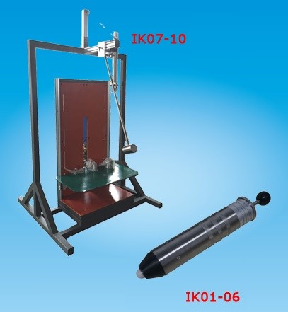
Figure 5. Test hammers used in laboratories for conducting IK tests
Impacts applied to the enclosure are evenly distributed across its walls. This test does not apply to components such as hinges or locks of the enclosure. The test is considered successful if the enclosure maintains its IP protection rating and dielectric strength, if removable covers can be attached and detached without difficulty, and if the doors can be opened and closed as they could before the test.
Every enclosure has an assigned IP protection rating determined during testing. The first digit of the IP rating indicates the protection provided by the enclosure against access to hazardous parts (e.g., live parts of switchgear) and the ingress of solid foreign particles (e.g., dust and dirt). The second digit relates to the ingress of water or other liquids into the enclosure. The testing procedure is detailed in standard PN-EN 60529, which includes all requirements and recommendations for conducting this test [8].
A talcum powder penetration test is performed to verify the ingress of solid foreign particles into enclosures with ratings of IP5X or IP6X. A test container is placed at the center of the enclosure's base, weighed before and after the test, and the difference in weight indicates the amount of talcum powder that entered the enclosure.
For water ingress testing, dry absorbent test paper is used. Colored paper or filter paper may also be used as it visually indicates moisture through discoloration [2,3]. For covers and doors designed for equipment installation, a strip of paper folded at a 90° angle is fixed to the base of the space as declared by the manufacturer. The proper depth for affixing the test paper in the protected space is 30 mm. If the enclosure has an unprotected gap, a piece of paper equal to or larger than the gap size is affixed to the protected surface.
The test is successful if the indicator paper or colored paper remains dry after the test [2,3].
In addition to IK and IP protection ratings, enclosures also possess other critical parameters. One such feature is the enclosure's resistance to heat and fire. This test evaluates the flammability of the enclosure material and is conducted in accordance with IEC 60695-2-10 and the details in IEC 60695-2-11 [6,7]. These standards precisely describe the testing procedure. Typically, this test is performed on samples taken from the enclosure since the dimensions of whole enclosures often make them unsuitable for testing in the apparatus. Samples are taken from predetermined locations on the enclosure structure, as required by the testing laboratory, usually from surfaces of the smallest thickness, with additional samples taken if the test needs to be repeated. Each sample is stored for 24 hours before testing at a temperature of 15°C to 35°C and relative humidity of 35% to 45%.
The test is conducted using a specialized device equipped with a heating element that applies a force of 1 N to the test sample mounted on a movable cart.
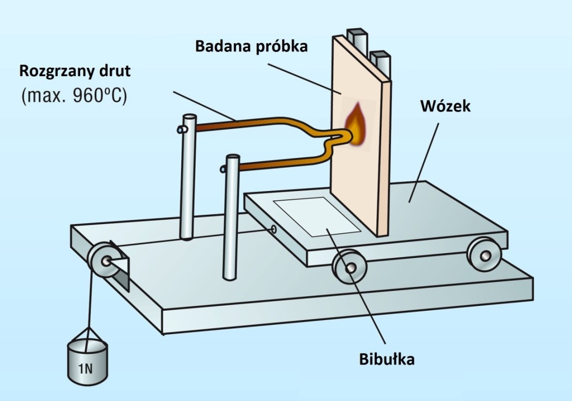
Figure 6. Glow-wire testing device in accordance with IEC 60695-2-11
The device is placed in a dark environment, typically with no air movement, so that any flames (if present) during the test are clearly visible. Before starting the test, the thermocouple is calibrated according to the requirements of section 6 of the IEC 60695-2-10:2000 standard. After each test, the tip of the wire is cleaned with a special brush to remove any residue.
The temperature of the glow-wire tip depends on the elements of the enclosure structure being tested:
- 960°C ± 15°C – Components supporting busbars (insulators) in a specific position,
- 850°C ± 15°C – Samples of enclosures designed for installation in wall cavities and niches,
- 650°C ± 15°C – All other parts, including those not supporting current-carrying conductors and those designed for installation in non-flammable walls.
The test, i.e., the application of the glow wire, lasts for 30 ± 1 seconds. After the wire is removed, the sample and the paper placed underneath are observed for an additional 30 seconds to check if the paper ignites (it should not) or if the sample ignites. If the sample ignites, the time from ignition to flame extinction is measured.
The test is considered successful if:
- No flame appears on the sample or the wiping paper,
- Any flames or glowing on the sample extinguish within 30 seconds after the removal of the heated wire.
For enclosures designed for outdoor use, resistance to ultraviolet (UV) radiation must be tested. UV resistance testing is performed according to Method A of ISO 4892-2. Enclosures are subjected to a single exposure cycle lasting a total of 500 hours. The compliance of plastic enclosures with the standard is verified by bending and impact testing of exposed enclosures using a Charpy hammer. The test is considered successful if at least 70% of the tested samples pass. This test is not required if the manufacturer provides material supplier data that meets the required parameters.
Metal enclosures and enclosures with external metal parts (composite enclosures) are tested for corrosion resistance. If the test cannot be performed on the entire enclosure, it is conducted on the metal part of the enclosure with structural characteristics identical to those of the enclosure. Metal hinges and fasteners are also tested during these procedures [2,3].
The enclosure is assembled as it would be in normal use during testing. Each enclosure or sample prepared for testing must be new and clean. The test itself is conducted using two different methods, separately for indoor and outdoor enclosures. The exposure test A is performed for indoor enclosures and external metal components used indoors [2,3]. This test consists of two procedures:
- The first procedure includes six 24-hour cycles where the component is exposed to moist hot air with 95% relative humidity and a temperature of 40°C ± 3°C.
- The second procedure involves exposing the component to salt mist twice, each for 24 hours at a temperature of 35°C ± 2°C.
Corrosion resistance testing for outdoor enclosures and metal components used outdoors involves two identical 12-day periods:
- The first phase consists of five 24-hour cycles in moist hot air with 95% relative humidity and a temperature of 40°C ± 3°C.
- The second phase involves seven 24-hour cycles in a salt spray at a temperature of 35°C ± 2°C.
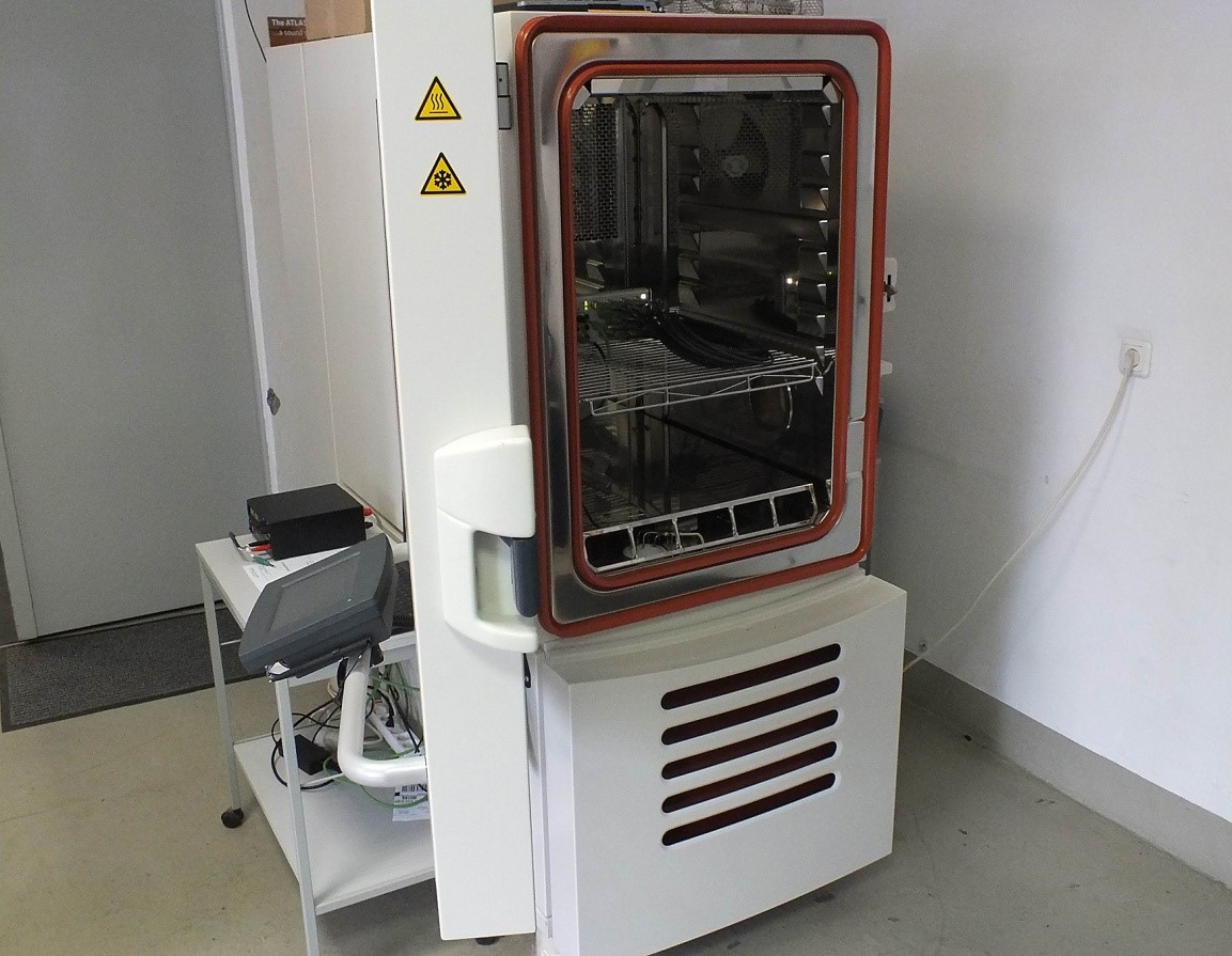
Figure 7. Testing equipment in accordance with IEC 60068-2-30
After completing the tests, the enclosure is washed in water for 5 minutes and then rinsed with distilled water. It is then dried, for example, using a fan to remove water droplets. Following this process, the sample is kept at room temperature for 2 hours. The test is considered successful if, upon visual inspection, there are no signs of rust, cracks, or damage on the tested sample. Minor deterioration of the protective coating (paint or varnish) is acceptable, as defined by ISO 4628-3.
Summary
This article presents and discusses the requirements for manufacturers of enclosures and the switchgear they house, as defined by standards for this type of product. The process of performed type tests (not all) is described, as outlined in the standards that prototype switchgear enclosures must comply with.
Designing and manufacturing switchgear enclosures in accordance with the SIST EN 62208 and SIST EN 61439 standards enables enclosure manufacturers to obtain certificates from accredited laboratories, confirming the performance of a specific product type. These type tests and the resulting certifications allow ETI to introduce new high-quality design solutions across European markets within the entire ETI group.


