New automatic production line for NV1 and NV2C fuse links
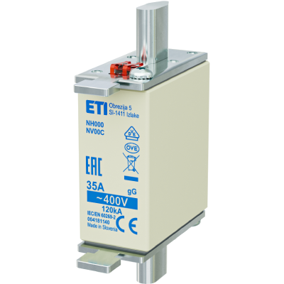
The new NV line is able to produce size 1 and 2C fuse links. This will reduce the cost price of the product and increase production capacity. An additional objective was to standardise production at ETI Polam and switch to KOMBI fuse link production only. All this will allow us to further grow our market share and profitability of the NV range.
| Uroš Kovač |


The sub-assembly is then inserted from the riveting unit by robot manipulation into the 4 units forcutting and welding the fuse elements (Unit 2). The line has 4 identical units where the fuse elementsare produced or ˝punched˝ from the pre-perforated and soldered strip according to the nominal flux of the fuse link. The unit then welds them to the metal subassembly of the contact knife blade with a base. The number of welding units was determined to achieve the desired line cycle. Each unit has & quot;recipes" for the rated currents of all characteristics and fusing element voltages. The recipes define the width of the fusion elements, the welding position per sub-assembly and the welding parameters themselves.
From the welding unit, the sub-assembly is then inserted, again by manipulation of the robot, into the base of the fuse link located in the circular table 1 (Unit 4). The addition of the base to the circular table 1 is carried out via Unit 3, which has been newly developed specifically for the needs of this line. In the design of the new automatic base removal system itself, we had in mind, first and foremost, to make the operation as simple and ergonomic as possible for the operators and optimal for the line itself. The warp transport trays are designed in such a way that the bases can only be oriented in a certain direction, which is then suitable for automatic manipulation in the line. From this unit, the base is also transferred by manipulation with a robotic arm to the bed of the circular table, where, as already stated, the welded subassembly from the welding units is inserted into it. The operation of inserting the welded sub-assembly into the base has received considerable attention during the manufacture of the device, as it is one of the most critical parts for the optimum operation of the fuse link. The optimum positioning, even at lower nominal currents, is further ensured by the sub-assembly gripping handles in the subsequent steps in the circular table. These grippers are also used to achieve the optimum position of the contact knife blade for the unit in the circular table 1, where the first cap is then applied. The caps are fed into the line via dosing units, where, regardless of type, the insert is also added. The types of caps are differentiated according to the material (Al or ISO) and the size of the fuse link (1 and 2C). The next units in the circular table 1 are then the screwing of the cover and the first measurement of the cold resistance, which, in the event of a fault, eliminates the bad piece at this stage. The presence of the screw and the achieved screw travel are also checked during the screwing process.
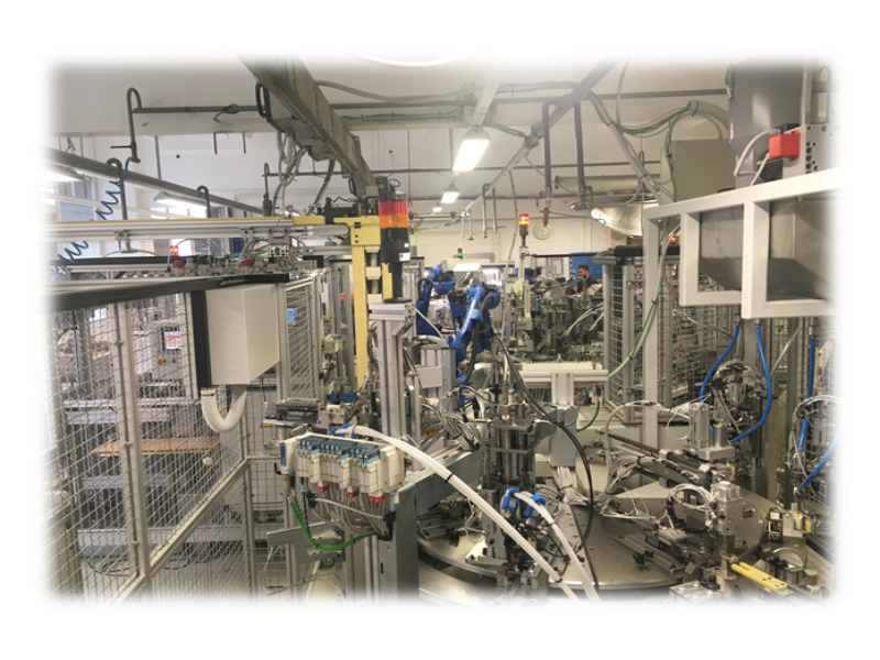
The fuse link is then transferred from circular table 1 to circular table 2 (Unit 5) by robotic manipulation. In circular table 2, the operations of circular table 1 are largely repeated. The second cap is added and screwed on. From this unit, the assembled fuse link goes into the indicator assembly unit (Unit 6). In this unit, the indicator spring is inserted and the indicator wire is routed. During manufacture, there are several inspection units to check that the indicator is correctly inserted. In the event of a loose or missing indicator, the line itself ejects the fusing element.
The almost fully assembled fuse link is then transferred from the indicator assembly unit via a conveyor belt to the sand blasting unit (Unit 7). This part is basically quite similar to the other blasting units on the RAPS, NV1C and NV00C lines. To achieve the desired line cycle, one more blasting point has been added than on the other lines (6 instead of 5). The unit also has a needle indentation measurement to ensure the correct level of fuse link sanding. However, as they say, "the devil is in the detail". As this is an NV1/2C size, the volume of the base to be filled with sand is 40% higher than for say an NV1C size. However, to achieve the desired line cycle, the blasting time was not allowed to increase by the same percentage as the increase in volume. In order to achieve the optimum times and also the optimum sand compaction in the fuse link, a new sand dosing method had to be developed that utilises the full volume of the hole in the cap for the sand flow. This has resulted in a much faster sand flow into the very base of the fuse link, and we can now fill the fuse link with a sufficient amount of sand in just 40 seconds.
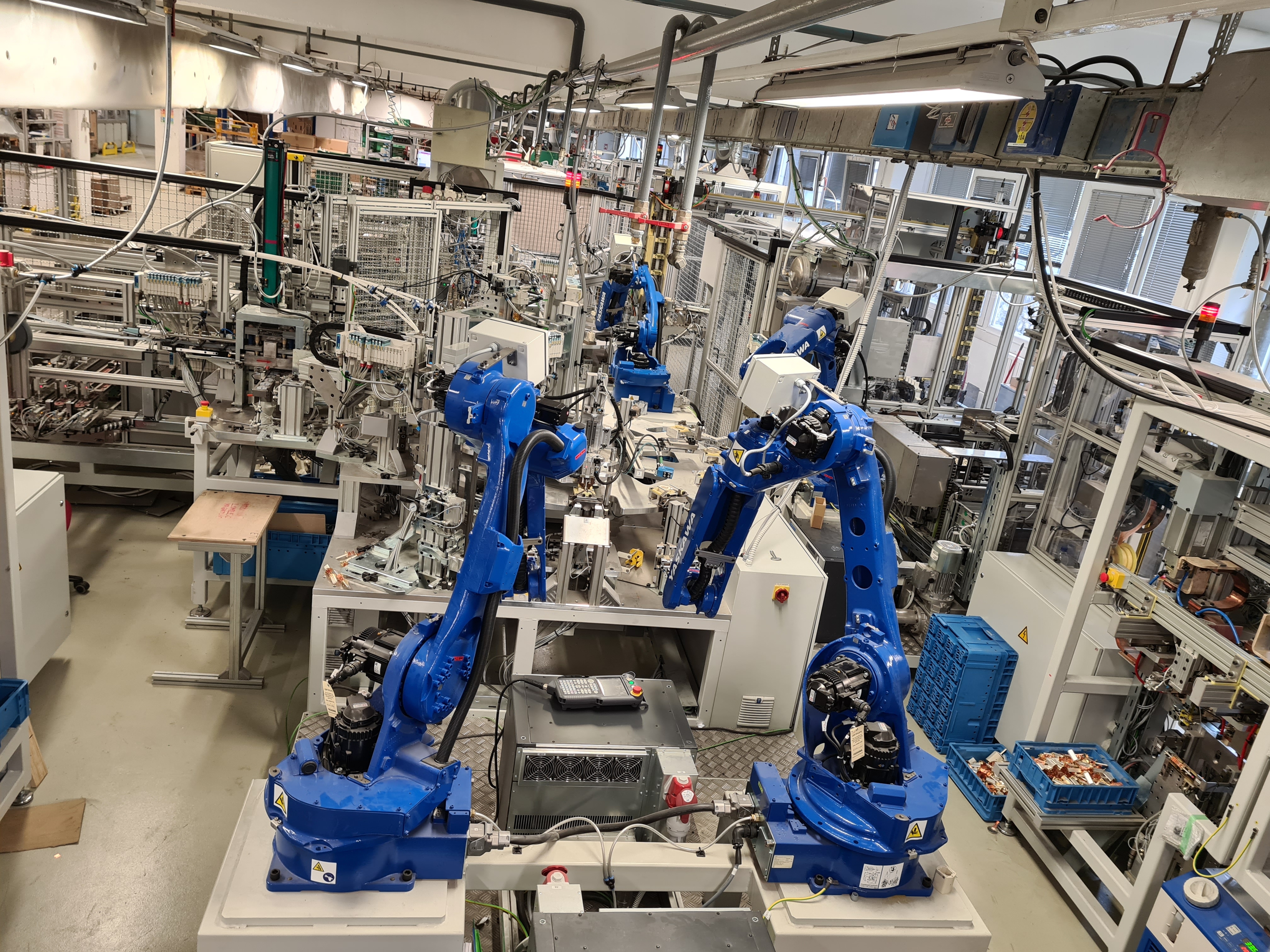
From the blasting unit, the fuse link then goes to the back of the line (Unit 8). In this unit, the fuse link is first subjected to a final cold resistance measurement. As part of this measurement, it shall be checked once more whether the installation of the vibration indicator on the blasting pad is still suitable. A date code and plate are printed, which are selected according to the type of fusing element. The route of the fuse link through the entire line concludes at the packing table. The ergonomics of the workplace were also kept in mind in the design of this part. This has been achieved by ensuring greater autonomy of operation of the line, which can run for up to 10 minutes without packaging.
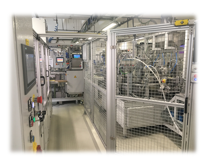
The entire line will be monitored by a control system which, as on the NV00C line, will allow traceability via a QR code. The QR code will record data for welding parameters, cold resistance, indicator suitability, sanding level, etc. A great deal of emphasis has also been placed on occupational safety on this line in the case of use and operation of the line. As can be seen from the unit-by-unit description of the operation of the line, there will be 6 robots operating on the line, which could pose a major hazard if safe operation is not given due attention. The areas where the robotic arms will operate are enclosed by a barrier. ETI Proplast has paid great attention to the access regime to ensure that it is optimally safe for the operators.


